
Too much protection: the port that worked until it was protected
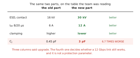
A 12 Gbps link passed compliance on the bare board. The team then upgraded the protection: higher peak pulse rating, higher kilovolt number, better clamping. On the selection table the new part won every column anyone was looking at. The link stopped meeting its eye mask, and nothing else on the board had changed.
The case: a port that worked until it was protected
A 12 Gbps link on a production board. It passed compliance with the protection footprints empty, which is the normal way to establish that the channel itself is sound.
The team then upgraded the ESD protection. The new part had a higher peak pulse rating, a higher kilovolt number and better clamping. Nobody was being careless. On the selection table it was better in every column anyone was looking at, and the ESD qualification afterwards was excellent.
The link then stopped meeting its eye mask. Nothing else on the board had changed.
Which gives the sentence this whole note is about: the part was better at the job it was bought for, and it broke the job the port was doing.
The column nobody read
On that selection table there is one column that decides whether a high speed link survives, and it is not a protection parameter. It is the junction capacitance.
It is easy to skip past, because it does not describe protection at all. Every other number on the row is about what happens during a discharge, which is an event lasting a hundred nanoseconds a handful of times in the life of the product. The capacitance describes what the part does for the rest of the time, which is all of it.
The mechanism: to a fast signal the part is a capacitor
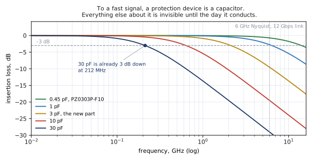
A protection device sitting on a signal line is a shunt capacitance across a matched pair. That is the entire model, and it is enough to predict everything that went wrong here.
The numbers get uncomfortable faster than people expect. At 30 pF the link is already 3 dB down before 250 MHz. Not at 5 GHz, not at 1 GHz. Before a quarter of a gigahertz. A part like that is completely fine on an I2C bus or a button, and it is unusable on anything with a serialiser behind it.
And at the 6 GHz Nyquist frequency of a 12 Gbps link, the classes separate brutally: 0.45 pF costs about 0.7 dB, 3 pF costs about 9.5 dB. That is not a degradation you can equalise your way out of.
Read it the other way round: the capacitance ceiling
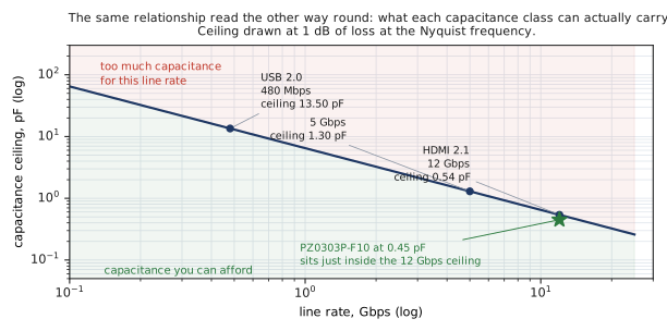
The useful version of this is not "what does my part cost me". It is "what is the most capacitance this line rate can carry", worked out before anybody opens a catalogue. Allowing 1 dB of loss at the Nyquist frequency:
- 480 Mbps, USB 2.0 high speed, ceiling about 13.5 pF
- 5 Gbps, ceiling about 1.3 pF
- 12 Gbps, HDMI 2.1, ceiling about 0.54 pF
Now the failure above is arithmetic rather than mystery. The new part was 3 pF against a 0.54 pF ceiling. It was roughly six times over budget before it was ever fitted, and no amount of excellent ESD performance was going to compensate.
It is also worth noting where our own part lands. PZ0303P-F10 at 0.45 pF sits just inside the 12 Gbps ceiling, not miles below it. It is correctly sized for the job rather than heroically overspecified, and that is the honest way to describe it.
What a correctly sized part actually costs
Choosing inside the ceiling does not mean the part is free. It means the cost is small and known, and we would rather print it than let somebody discover it.
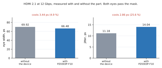
On a real HDMI 2.1 link at 12 Gbps, measured with and without PZ0303P-F10 in place:
- Eye width goes from 69.92 ps to 66.48 ps. The part costs 3.44 ps, which is 4.9 percent.
- Jitter goes from 11.18 ps to 14.04 ps. The part costs 2.86 ps, which is 25.6 percent.
- Both eyes pass the mask.
Eye width and jitter are exactly the two parameters a shunt capacitance degrades, and both moved in the direction and by roughly the amount the model says they should. That agreement matters more than the individual numbers, because it means the model above can be trusted to predict a part you have not fitted yet.
Being straight about the third number
There is a third parameter in those captures and it did something we are not going to dress up. Eye height measured higher with the device fitted than without it.
We are not claiming that as an improvement, because it is not one. A shunt capacitance has no mechanism by which it would add eye height. It sits inside the spread you get between two captures of the same link, and the honest reading is that eye height did not move.
It is in the datasheet anyway, and it is described that way, because a measurement you only publish when it flatters you is not a measurement anybody should trust.
The fix: let the data rate choose the capacitance class
The selection order that prevents this failure is two steps, and the order is the whole point.
- Let the data rate choose the capacitance class. Work out the ceiling first, from the line rate and the trace impedance, before any part number is on the table. This is a signal integrity decision and it has one answer.
- Then take the best clamping available inside that class. Within the parts that fit under the ceiling, now optimise for the protection parameters: contact rating, peak pulse current, clamping voltage, dynamic resistance.
Done in that order you get the best protection the link can carry. Done in the other order you get the failure at the top of this note, which can be stated in one line: buying more clamping than the class allows is how a protected port fails compliance.
And on slower lines, do the opposite
The mirror image of this mistake is just as expensive and much less discussed. Do not pay for capacitance you do not need.
Below about 480 Mbps the ceiling is over 13 pF, which means an ultra low capacitance part is buying you nothing at all on the signal while costing you money and, more importantly, costing you junction area. Take the larger junction and the better clamping instead. On a slow line that is a straightforwardly better part.
Ultra low capacitance is not a mark of quality. It is a specialisation, and on a line that does not need it you are paying for it twice: once at the purchase order and once in the protection you did not get.
What we print, and why
Most ESD datasheets stop at a capacitance number. That number is necessary and it is not sufficient, because the question a signal integrity engineer is actually going to be asked is what the part does to the channel.
So on PZ0303P-F10 we publish the measured S21 out to 10 GHz, and the HDMI 2.1 eye at 12 Gbps with and without the part fitted, in the datasheet itself. Those are the two things that get asked for, and printing them means nobody has to take our word for the capacitance figure.
And the practical offer: tell us the data rate and the trace impedance and we will give you the capacitance ceiling before we recommend a part, rather than after. That is a two minute calculation and it is the one that decides whether the rest of the conversation is worth having.
The short version
- A protection part can be better at protecting and still break the port, because the column that decides a high speed link is capacitance and it is not a protection parameter.
- To a fast signal the device is a shunt capacitor. At 30 pF the link is 3 dB down before 250 MHz.
- Work out the capacitance ceiling from the line rate first: about 13.5 pF at 480 Mbps, 1.3 pF at 5 Gbps, 0.54 pF at 12 Gbps.
- The part in this case was 3 pF against a 0.54 pF ceiling, roughly six times over budget before it was fitted.
- A correctly sized part still costs something. At 12 Gbps ours costs 3.44 ps of eye width and 2.86 ps of jitter, measured, and both eyes still pass.
- Choose the capacitance class from the data rate, then take the best clamping inside that class. That order, not the other one.
- Below about 480 Mbps do the opposite: take the larger junction and the better clamping, because ultra low capacitance buys you nothing there.