
Air is not contact: the pass that only held at 40 percent humidity
The product has a plastic bezel and no exposed metal, so there is nothing to put a probe tip on and the whole thing is qualified by air discharge. Ten discharges per point, every seam, every button, at the required level. No failures, signed off. Then the field reports lock-ups, and they cluster in winter and in the dry regions.
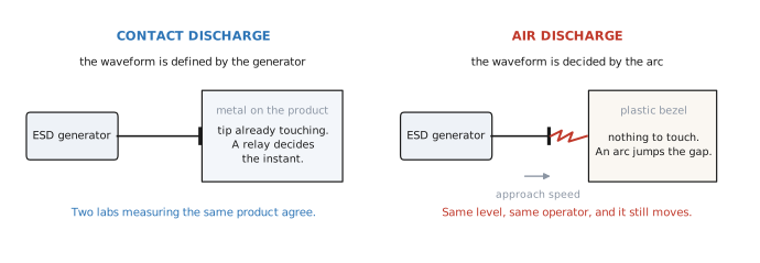
The product, and why it had to be tested by air
A sealed consumer product with a plastic bezel. No exposed screws, no metal trim, no connector shell within reach of a user. There is genuinely nothing to put a probe tip on.
That is not a mistake in the design, and it is common. It does mean that the only method available is air discharge, where the probe is charged, brought towards the product, and an arc jumps the gap on its own. The product was qualified that way, at the required level, ten discharges per point, on every seam and every button. Clean report.
The report passed. The field did not agree.
Lock-ups and resets started coming in. Not destroyed units, which matters, but soft failures that needed a power cycle. Two patterns were obvious once somebody sorted them properly:
- They clustered in winter.
- They clustered in the dry regions.
Nothing about the design had changed between the pass and the returns. The same hardware behaved differently in a different atmosphere, and the qualification had been done in an atmosphere that is held constant by regulation.
What contact discharge gives you: a number inside a tolerance
In contact discharge the tip is already touching the product before anything happens. A relay inside the generator decides the instant of the discharge, so the current is set by the generator rather than by the air.
That is why the standard can put a table around it. IEC 61000-4-2 Table 3 pins the whole waveform at each level. At level 4, which is 8 kV:
- first peak current 30 A, ±15 percent
- rise time 0.8 ns, ±25 percent
- current at 30 ns 16 A, ±30 percent
- current at 60 ns 8 A, ±30 percent
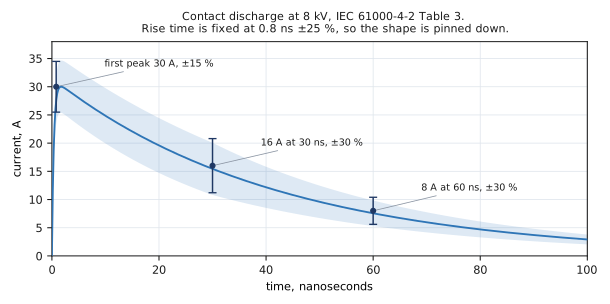
The consequence is worth stating plainly. A contact discharge pass is a measurement. Send the same product to a different lab and you get the same answer, because the thing being applied is defined to within a stated tolerance.
What air discharge gives you: an arc, and whatever the arc decides
In air discharge nothing is touching. The probe approaches, the field between the tip and the product rises, and at some point the air breaks down and an arc forms. Everything about that arc is decided by the air, the geometry and the speed of the approach.
The standard does not hide this. Its own annex on the spark says the rise time of the discharge current can vary from less than 1 ns to more than 20 ns as the approach speed is varied. Then it says the part that surprises people:
Keeping the approach speed constant does not result in constant rise time. For some voltage and speed combinations, the rise time still fluctuates by a factor of up to 30.
So this is not a matter of operator skill or of buying a better robot. One test level, one operator, one product, and the thing actually being applied still moves across a range of more than an order of magnitude.
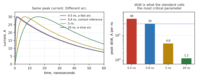
Why that matters: it moves the parameter that does the damage
If the rise time only affected how the event looked on a scope, none of this would be worth an article. It does not. The standard names the rate of change of current as the most critical parameter, and rate of change of current is set almost entirely by rise time.
Work it through with the numbers above, holding the peak at 30 A. A 20 ns arc gives about 1.2 A per nanosecond. A 0.5 ns arc gives about 48. That is a factor of forty in the quantity that couples into your board and drives the voltage across every parasitic inductance in the discharge path.
Which gives two conclusions that need to sit together, because taking either one alone gets you into trouble:
- A slow arc is a gentle test. It can be considerably gentler than the contact discharge at the same voltage, which is how a product passes air and fails in service.
- A fast arc is harsher than contact. At a sub-nanosecond rise it exceeds the contact reference, which is how an air test occasionally fails a product that is actually fine.
And the part that makes it a real problem: you do not choose which one you got, and the report does not record it. A pass at 8 kV air might have been a much harder test than 8 kV contact, or a much easier one. The document looks identical either way.
And the laboratory is held at a humidity your customer is not
An arc is a breakdown in air, so it depends on the state of the air. That is why the standard specifies the conditions for air discharge testing in clause 8.1.2: ambient temperature 15 to 35 °C, atmospheric pressure 86 to 106 kPa, and relative humidity 30 to 60 percent.
That range is there to make the test reproducible, and it does help. It also means the qualification happens in conditioned air, and the product does not live in conditioned air.
The standard goes further and tells you what the dry case looks like. Table A.1, its own guideline for choosing a test level, ties the level to the humidity you expect and the materials present:
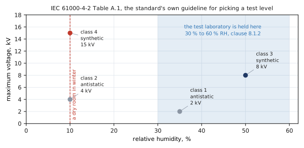
Read the two points at 10 percent humidity against the shaded band. The conditions that produce the highest electrostatic voltages are conditions the test is not performed in. A dry room with synthetic materials reaches 15 kV, and the laboratory is held between 30 and 60 percent.
That is the whole case in one figure. Failures clustering in winter and in dry regions is not a coincidence to be explained away. It is the difference between the atmosphere in the report and the atmosphere in the customer's living room.
None of this is a criticism of the test house
Worth being clear, because this material is easy to misread as blaming somebody. The laboratory did exactly what the standard asks. Air discharge is in IEC 61000-4-2 on purpose, because some products have no metal to touch and they still have to be tested somehow.
The standard itself states that contact discharge is the preferred method, and everything above is the standard explaining why. Air discharge is the fallback for products that cannot take the preferred method. It is not a second opinion of equal weight, and a report cannot tell you more than the method underneath it can.
What to do about it
- If any part of the product can take contact discharge, do that part by contact. Connector shells, screws, metal trim, exposed shielding. Mixed reports are normal and the contact rows are the ones with real information in them.
- Where only air is possible, take margin instead of the test. You cannot control the arc, so stop trying to and buy headroom instead. Specifying twice the required level is the practical answer, and on a high speed line it is close to free.
- Do not read an air pass as equal to a contact pass at the same voltage. It is a weaker statement about the product, and the gap is not a fixed number you can correct for.
- If failures track the season or the region, believe the pattern. Humidity is the mechanism, it is in the standard's own annex, and it will not reproduce in a conditioned laboratory no matter how many times you re-run the test.
Comparing two vendors, and what we print
When two protection parts are put side by side, compare the contact figure to the contact figure. It is the number the standard makes repeatable, so it is the only one where a difference between two datasheets means what it appears to mean.
An air number is usually higher, and it is higher for a reason that has nothing to do with the silicon being better. Comparing one vendor's air rating against another vendor's contact rating is not a comparison at all.
We print both, as two separate rows on page one, so nobody has to work out which one they are holding. On the PZ0303P-F10 that is ±16 kV contact and ±21 kV air. Against an 8 kV requirement the contact figure alone is twice the level, and it costs 0.45 pF to have.
The short version
- Contact discharge is a measurement. Table 3 bounds the peak, the rise time and the current at 30 and 60 ns, so two laboratories agree.
- Air discharge is an arc. The standard says its rise time runs from under 1 ns to over 20 ns, and that holding the approach speed constant still leaves a factor of up to 30.
- Rise time sets the rate of change of current, which the standard calls the most critical parameter. Across that range it varies by about forty times.
- A slow arc is gentler than contact and a fast arc is harsher, and neither the operator nor the report knows which one happened.
- Air discharge testing is specified at 30 to 60 percent relative humidity, while the standard's own Table A.1 puts the worst case at 10 percent.
- Failures that cluster in winter or in dry regions are the humidity difference, not a coincidence.
- Compare contact to contact between vendors. Where only air is possible, buy margin rather than trusting the number.