
Surge is not ESD: the port that passed 8 kV and died on a cable
The qualification report is clean. Contact discharge to every exposed pin, up to the required level, no failures, criteria A throughout. Then units start coming back with the interface pin shorted, and the common factor is not a person touching the connector. It is a long cable run.
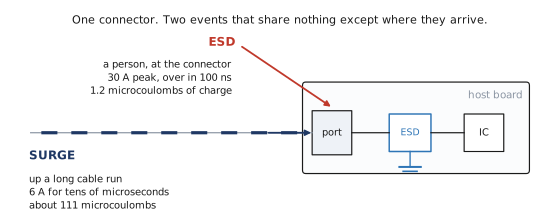
What was protected
An external interface on a piece of equipment. A connector, a low capacitance ESD array right behind it, then the interface IC. This is the correct arrangement and the correct part for it. Nothing in the layout is wrong, and nothing in the schematic would be picked up in review.
The board was qualified against IEC 61000-4-2, which is the standard everybody means when they say "ESD testing", and it passed.
The report was clean. The returns were not.
Contact discharge to every exposed pin, up to the required level. No failures, no degradation, criteria A throughout. On paper the port is protected.
Then units start coming back with the interface pin shorted. When somebody finally sorts the returns by installation rather than by date, the pattern is obvious and it has nothing to do with people: the failures are on the installations with a long cable run.
That single fact settles it. The test that was passed and the event that caused the failure were not the same event. Everything else in this note is about why one part can be excellent at the first and undersized for the second.
Two events, one connector
A discharge from a person and a surge coming up a cable both arrive at the same pin, and both are handled by the same component, so they get discussed as one topic. They are not one topic. They differ in the thing that actually decides whether silicon survives, which is how long the current lasts.
- ESD, IEC 61000-4-2. A charged person or object touches the connector. At 8 kV contact the generator is 150 pF charged to 8 kV, so it delivers 30 A of peak current and the whole event is finished inside about 200 ns. It happens a handful of times in the life of the product.
- Surge, IEC 61000-4-5. Energy induced onto a cable by switching or by lightning somewhere else on the run. The 8/20 microsecond waveform, tens of microseconds long, and it can repeat every time the plant next door starts a motor.
A long cable is an antenna and a conductor. It is the reason the second event exists at all, and it is why a short cable installation of the same product never showed the failure.
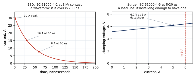
One is a waveform. The other is a load line.
That difference is not presentational. It tells you what each event does to the part.
For ESD you plot current against time, because the event is a transient with a shape. It is over before the die has warmed up, so what matters is how fast the device turns on and how high the voltage gets while it does.
For surge you plot voltage against current, because the event lasts long enough to reach a steady operating point. The device sits somewhere on that line for tens of microseconds. It has a load line in the way a resistor has one, and the die heats up the entire time it is there.
Both of these are published measurements on the PZ0303P-F10, not simulations. They are in the datasheet as Fig 4 and Fig 5, and they are two different kinds of plot because they are two different kinds of event.
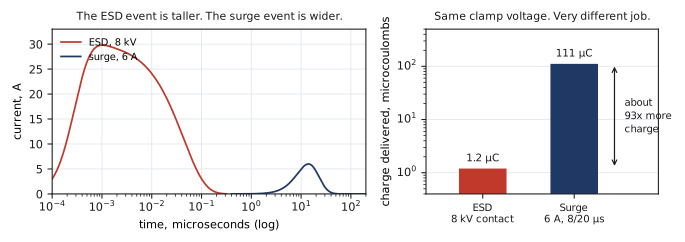
How much charge each one actually moves
The ESD figure needs no modelling at all. An 8 kV contact discharge comes from a 150 pF generator charged to 8 kV, and charge is capacitance times voltage, so the event moves 1.2 microcoulombs. That is the whole discharge.
A 6 A surge on the 8/20 microsecond waveform moves about 111 microcoulombs, which is roughly ninety times more charge. The peak current is five times smaller and the charge is ninety times larger, purely because the event is wider.
This is the trap in one sentence. Peak current is the number that gets quoted and duration is the number that does the damage. A part selected on peak current alone will look enormously overspecified for the surge and will not survive it.
The same silicon, two very different ratings
Open the Limiting Values table of the PZ0303P-F10 and both numbers are there, one page, two rows:
- ±16 kV contact discharge, and ±21 kV air, per IEC 61000-4-2
- 6.0 A peak pulse current at 8/20 microseconds, per IEC 61000-4-5
Both are true, and they are not in tension with each other. They are the same die measured against two events that ask completely different things of it. A reader who takes only the first number away has been told the truth and has still drawn the wrong conclusion.
It is worth saying plainly that 6 A is a modest surge rating, and we print it anyway. A part that is genuinely excellent at one event and ordinary at the other should say so on its own front page, because the alternative is the failure this note describes.
Why heat is what decides it
Compare the two events at the device and the clamping voltage barely moves. The datasheet gives both: 6.1 V under a 16 A TLP pulse, and 6.2 V under a 5 A surge. Three times the current, and a tenth of a volt between them.
So the device is doing the same thing electrically in both cases, and yet one event it shrugs off and the other sits at its rated limit. Clamping voltage cannot be what separates them, because clamping voltage is the thing that did not change.
What changes by two orders of magnitude is how long the die has to carry the current. Power is voltage times current, and energy is power times time. At roughly the same clamping voltage and a fifth of the current but ninety times the charge, the surge puts far more energy into the same piece of silicon, and it does it slowly enough that the heat has nowhere to go but into the junction.
ESD damage, when it happens, is usually dielectric. Surge damage is thermal. That is why the two ratings scale with different things: the ESD number tracks how the device turns on, and the surge number tracks the die area and how well the package gets heat out of it.
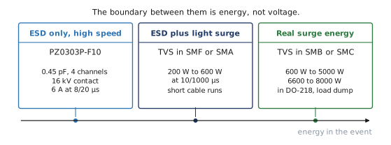
Three classes, and the boundary is energy
Once you accept that duration is the variable, the selection stops being a judgement call and becomes a question with an answer.
- ESD only, on a high speed line. The port is inside an enclosure, the cable is short, and the signal cannot tolerate loading. Here capacitance is the binding constraint and an ultra low capacitance array is the right part. PZ0303P-F10 at 0.45 pF and 4 channels.
- ESD plus light surge. A short external run with modest exposure. A TVS in SMF or SMA, which across our line runs 200 W to 600 W at 10/1000 microseconds.
- Real surge energy. Long external cable, industrial environment, or an automotive load dump. A TVS in SMB or SMC, 600 W to 5000 W, and DO-218 at 6600 W to 8000 W where the event is a load dump.
Notice that the classes are separated by energy handling, and that capacitance moves the opposite way. The parts that survive the most energy have the most junction area and therefore the most capacitance. That is the real trade, and it is why one component cannot sit at both ends of this list.
Where both events are real, fit both parts
This is the conclusion people resist, because it costs a line on the bill of materials. An ESD array is not made redundant by a TVS, and a TVS is not made redundant by an ESD array.
The TVS is the part with the die area to absorb the surge, and it is too slow and too capacitive to be the only thing protecting a fast line. The ESD array turns on quickly and loads the signal with a fraction of a picofarad, and it does not have the silicon to sit in a surge for twenty microseconds. On a port that is genuinely exposed to both, the TVS goes at the connector to take the energy and the low capacitance array goes next to the IC to catch what gets past it.
Fitting one and calling the port protected is exactly how a clean qualification report turns into a field return.
What to establish before choosing
Three questions, and none of them is about the protection device.
- How long is the cable, and does it leave the enclosure? An internal ribbon and a thirty metre field run are not the same port even when the schematic is identical.
- What is on the other end of it, and what else shares the run? Inductive loads, motor drives and long parallel runs are what put surge energy onto a signal cable.
- What data rate does the line carry? This sets the capacitance budget, and the capacitance budget decides how much of the job the low capacitance part can take.
Answer those and the class picks itself. Skip them and the choice gets made on the one number that happens to be printed largest.
The short version
- Passing IEC 61000-4-2 says nothing about IEC 61000-4-5. They are different events and only one of them was on the test plan.
- ESD is a waveform, over in 200 ns. Surge is a load line, lasting tens of microseconds. The plots are different kinds of plot for a reason.
- An 8 kV discharge moves 1.2 microcoulombs. A 6 A surge at 8/20 microseconds moves about ninety times that, at a fifth of the peak current.
- Clamping voltage barely changes between the two. What changes is how long the die carries the current, and heat is what kills it.
- Pick the class by the event, not by the voltage. Where both events are real, fit both parts.
- If a cable run correlates with your returns, look at the surge rating before you look at anything else.